1. Background
- Q1: What does transport-layer protocol do?
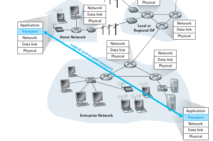
A transport-layer protocol provides for logical communication between application processes running on different hosts.
- Q2: What is logical communication?
Logical communication means from an application’s perspective it is as if the hosts running the processes were directly connected but in reality, the hosts may be on opposite sides of the planet
- Q3: Where is transport-layer protocol implemented?
At end systems
- Q4: What is the mean of communication between application layer ↔ transport layer?
Via an interface named SOCKET
- Q5: How many protocols are there in the transport layer?
TCP and UDP
- Q6: A quick description when sending data between processes?
On the sending side:
Transport layer convert application-layer message into smaller chunk and add header to create a segment
Transport layer then passes the segment to network layer (I’ll stop right here and continue to introduce in network layer chapter)
On the receiving side:
- The network layer extracts the transport-layer segment then segment up to transport layer
- Q7: Relationship between transport layer and network layer?
A transport-layer protocol provides for logical communication between application processes running on different hosts.
A network-layer protocol provides for logical communication between hosts.
- Q8: What is the most fundamental responsibility of transport layer protocol?
Extend IP’s delivery service between two end systems → a delivery service between two processes running on the end systems
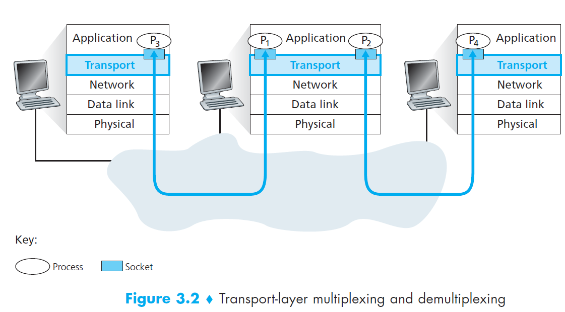
Extending host-to-host delivery → process-to-process delivery is called transport-layer multiplexing and demultiplexing.
2. Multiplexing and Demultiplexing
- Q1: Short description about socket?
Each process can have one more multiple sockets
Sockets is a intermediary between processes and transport layer
Each socket has a unique identifier
- Q2: How the multiplexing works?
The job of gathering data chunks at the source host from different sockets
Encapsulating each data chunk with header information (that will later be used in demultiplexing) to create segments
Then passing the segments to the network layer
- Q3: How the demultiplexing works?
The job of examining some set of fields in a segment to identify the receiving socket
Delivering data to correct socket
- Motivation
In multiplexing/demultiplexing, What factors do we need to identify correct sockets?
- Solution
We know that transport-layer multiplexing requires
- Sockets have unique identifiers
- Each segment has special fields that indicate the socket to which the segment is to be delivered
These special fields are the source port number field and the destination port number field
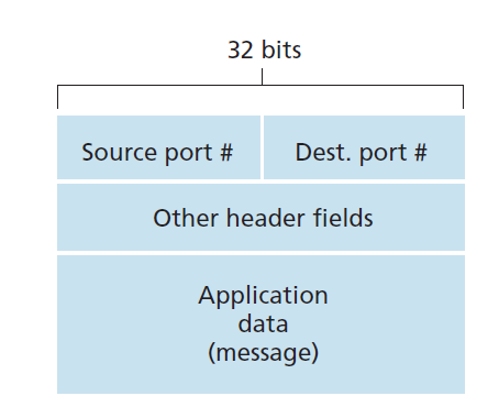
Each port number is a 16-bit number, ranging from 0 to 65535
The port numbers ranging from 0 to 1023 are called well-known port numbers and are restricted
2.1 Connectionless
- UDP socket is fully identified by a two-tuple consisting of a destination IP address and a destination port number
- If two UDP segments have
- Different source IP addresses
- and/or source port numbers,
- but have the same destination IP address and destination port number
- then the two segments will be directed to the same destination process via the same destination socket.
2.2 Connection-Oriented
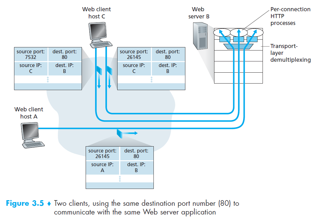
- TCP socket is identified by a four-tuple: (source IP address, source port number, destination IP address, destination port number).
- If two TCP segments have
Different source IP addresses
and/or source port numbers,
but have the same destination IP address and destination port number
then the two segments will be directed to the two different process via the same destination socket.
3. Connectionless Transport: UDP
- Q1: Why is UDP considered connectionless?
UDP is said to be connectionless because there is no handshaking between sending and receiving transport-layer entities before sending a segment
- Q2: List some applications use UDP?
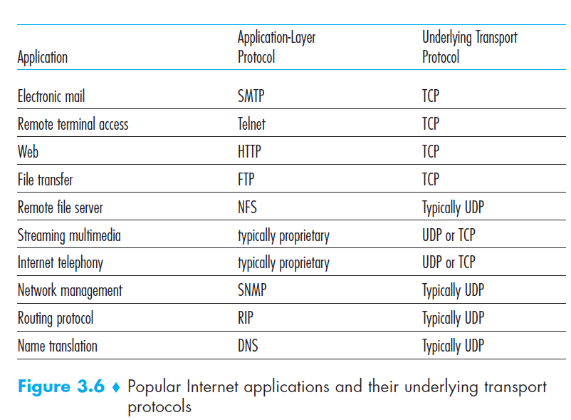
- Q3: Why an application developer would ever choose to build an application over UDP rather than over TCP?
Finer application-level control over what data is sent and when
No connection establishment
No connection state
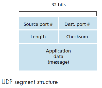
Small packet header overhead (UDP only has 8-bytes header)
- Q4: How to make reliable data over UDP?
This can be done if reliability is built into the application itself (for example, by adding acknowledgment and retransmission mechanisms)
Q5: UDP Segment Structure
4. Principles of Reliable Data Transfer (*)
- Q1: What does RDT do?
- It is the responsibility of a reliable data transfer protocol to implement service abstraction
- The service abstraction provided to the upper-layer entities is that of a reliable channel through which data can be transferred
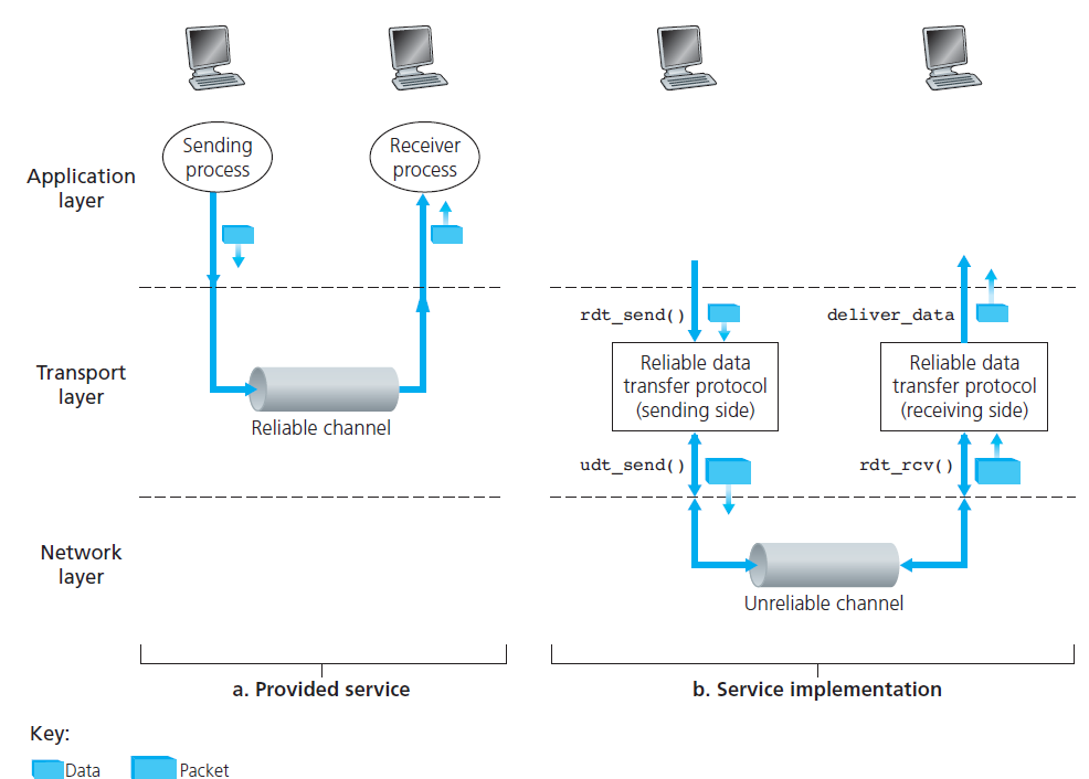
- Even though lower-layer of RDT can be unreliable channel, RDT is also responsible for making sure data transferred is safe.
- Q2: What is implementation of RDT?
ARQ (Automatic Repeat reQuest) protocols
Three additional protocol capabilities are required in ARQ protocols to handle the presence of bit errors:
Error detection: allow the receiver to detect when bit errors have occurred.
Receiver feedback: the receiver to provide explicit feedback to the sender. The positive (ACK) and negative (NAK) acknowledgment
Retransmission: A packet that is received in error at the receiver will be retransmitted by the sender
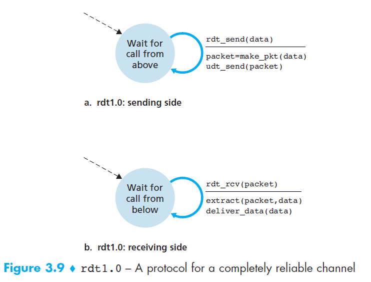
- From now on, we’ll use The finite-state machine (FSM) to describe RDT protocols:
- Three main factors are used in FSM: states, events and actions
- Switch from state 1 to state 2 is called a transition
- Notation
- Circle: states
- Arrow: transitions
- Above horizontal line: events
- Below horizontal line: actions when events occur
rdt 1.0 - Reliable Data Transfer over a Perfectly Reliable Channel
rdt 2.0 - Reliable Data Transfer over a Channel with Bit Errors
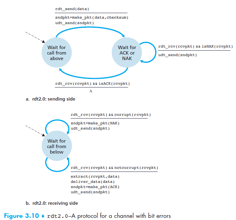
- It is important to note that when the sender is in the wait-for-ACK-or-NAK state, it cannot get more data from the upper layer
- Because of this behavior, protocols such as rdt2.0 are known as stop-and-wait protocols.
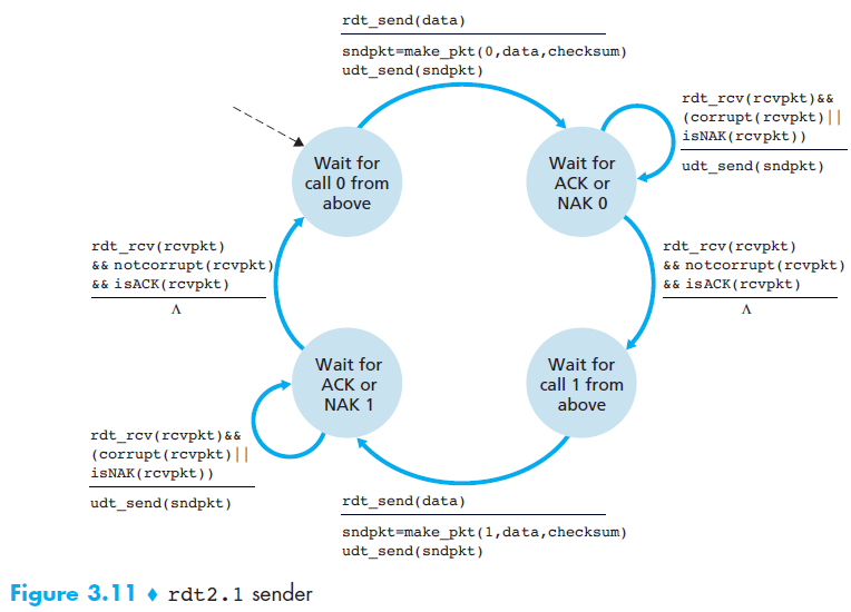
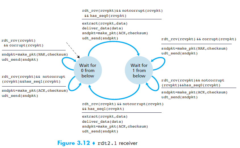
rdt 2.1
- Motivation
- In protocol rdt2.0, we haven’t accounted for the possibility that the ACK or NAK packet could be corrupted!
- Solution
- The sender simply to resend the current data packet when it receives a garbled ACK or NAK packet. (This would introduce duplicate packets)
- to add a new field to the data packet and have the sender number its data packets by putting a sequence number
- For this simple case of a stop-and-wait protocol, a 1-bit sequence number will suffice
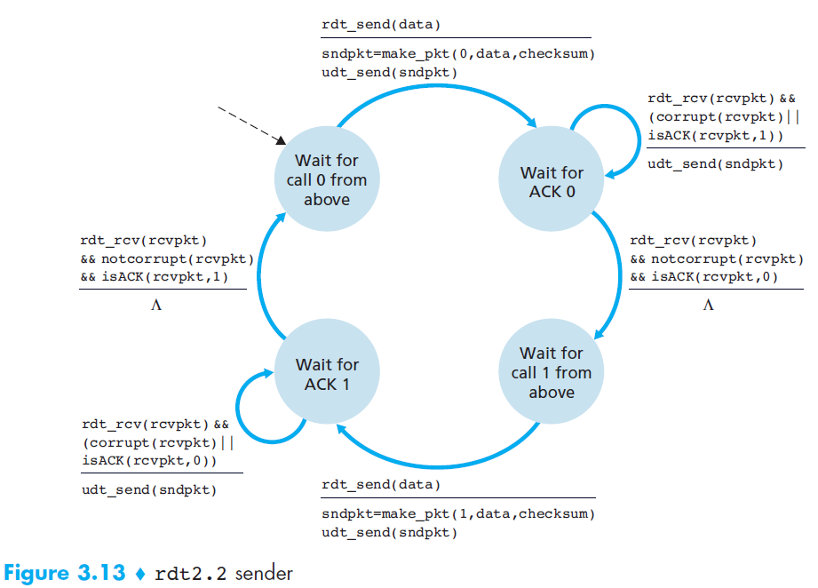
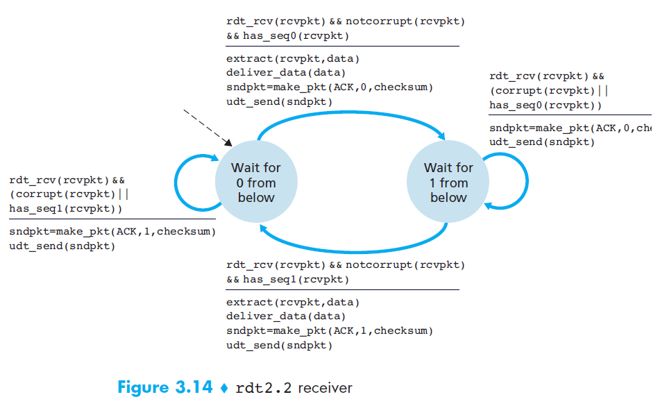
rdt 2.2 NAK-free protocol
- Motivation
- A NAK only means “the next packet was not received correctly.”
- Solution
But the same effect can be achieved if the receiver just sends a duplicate ACK for the last correctly received packet.
→ This allows us to eliminate NAK entirely and use only ACK messages.
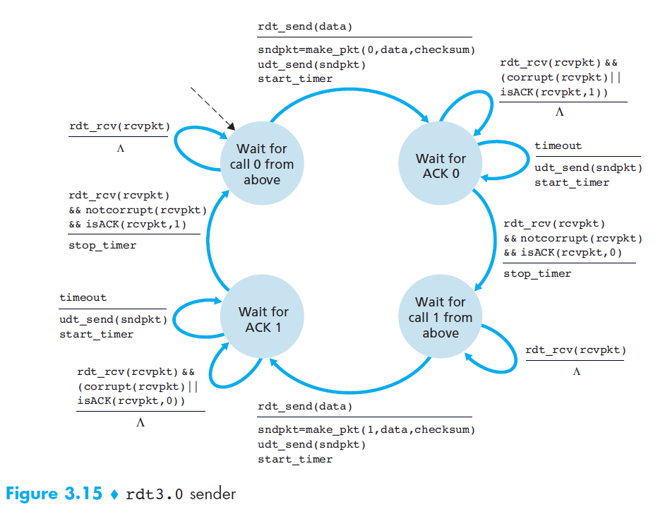
rdt 3.0 - Reliable Data Transfer over a Lossy Channel with Bit Errors
- Motivation
- Two additional concerns must now be addressed by the protocol:
- How to detect packet loss
- What to do when packet loss occurs (solved by rdt 2.0)
- Two additional concerns must now be addressed by the protocol:
- Solution
- If the sender is willing to wait long enough so that it is certain that a packet has been lost, it can simply retransmit the data packet
- Implementing a time-based retransmission mechanism requires a countdown timer that can interrupt the sender after a given amount of time has expired
- rdt3.0 is sometimes known as the alternating-bit protocol.
- Q1: How long must the sender wait to be certain that something has been lost?
At least as long as a round-trip delay between the sender and receiver
- Q2: In rdt3.0, it introduces the possibility of duplicate data packets?
Happily, protocol rdt2.2 already has enough functionality (that is, sequence numbers) to handle the case of duplicate packets.
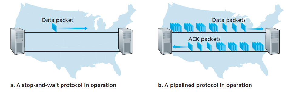
5. Pipelined Reliable Data Transfer Protocols
- Motivation
- At the heart of rdt3.0’s performance problem is the fact that it is a stop-and-wait protocol
- To appreciate the performance impact of this stop-and-wait behavior, (check 3.4.2 Computer networking, A top-down approach 6th edition)
- Key takeaways,
- with a packet of 8000 bits length and the transmission rate of 1 Gbps
- The sender was busy only 2.7 hundredths of one percent of the time! (0.00027)
- The problem with stop-and-wait is low efficiency due to idle time.
- Solution
Rather than operate in a stop-and-wait manner, the sender is allowed to send multiple packets without waiting for acknowledgments.
The solution is pipelining
Pipelining requires:
- A larger range of sequence numbers
- Buffering at both sender and receiver
- Different error recovery strategies: Go-Back-N or Selective Repeat
5.1 Go-Back-N (GBN) (*)
Before we dive deep into this protocol. You can try and play around its demo at: https://computerscience.unicam.it/marcantoni/reti/applet/GoBackProtocol/goback.html
GBN protocol is itself as a sliding-window protocol
Data structure
- A N is the window size
- A base is the sequence number of the oldest un-ack packet
- A nextseqnum is the smallest unused sequence number
- So, we now have 4 intervals in the range of sequence number
[0, base - 1]: packets that have already been transmitted and acknowledged[base, nextseqnum - 1]: packets that have already been sent out and but not yet acknowledged[nextseqnum, base + N - 1]: packets can be sent immediately[base + N, $\infty$]: packets cannot be used until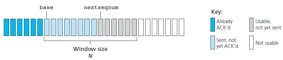
State machine
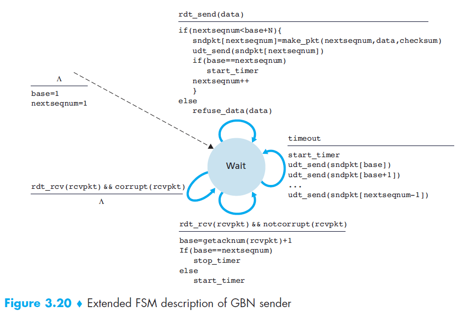
Event
- The GBN sender reacts to three events:
- Invocation from above: If the window is not full, a new packet is created and sent. If full, the sender rejects the data (or buffers it in real systems).
- Receipt of an ACK: GBN uses cumulative ACKs, meaning that an ACK for packet n confirms all packets up to n.
- Timeout event: If a timeout occurs, the sender retransmits all unacknowledged packets. GBN maintains only a single timer for the oldest outstanding packet. The timer is restarted when an ACK is received (if unacknowledged packets remain), or stopped if none remain.
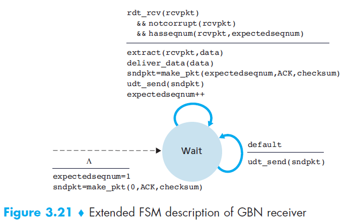
- The GBN receiver is much simpler:
- If the expected packet
narrives correctly, it delivers it to the upper layer and sends ACK(n). - If an out-of-order packet arrives (e.g.,
n+1when expectingn), it is discarded and the receiver resends the last ACK (e.g., ACK(n)) - Do not buffer out-of-order packets, making the receiver design simple. It only keeps track of expectedseqnum.
- Example: With a window size of 4, if packet 2 is lost, packets 3, 4, and 5 are discarded until packet 2 is correctly retransmitted by the sender.
- If the expected packet
- The GBN sender reacts to three events:
5.2 Selective Repeat (SR)
Before we dive deep into this protocol. You can try and play around its demo at: https://computerscience.unicam.it/marcantoni/reti/applet/SelectiveRepeatProtocol/selRepProt.html
Motivation
- In GBN, When the window size and bandwidth-delay product are both large
- A single packet error can thus cause GBN to retransmit a large number of packets
Solution
- Selective-repeat protocols avoid unnecessary retransmissions by having the sender retransmit only those packets that it suspects were received in error (that is, were lost or corrupted) at the receiver.
Data structure
- Almost same as GBN
Event
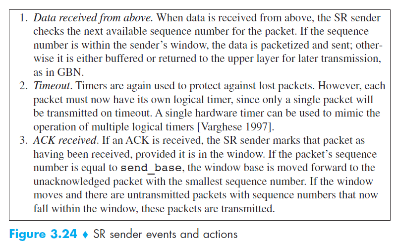
Compared to GBN
- Go-Back-N (GBN):
- The receiver discards out-of-order packets.
- When a timeout occurs, the sender resends all unacknowledged packets.
- The receiver does not need a buffer (only maintains one variable:
expectedseqnum).
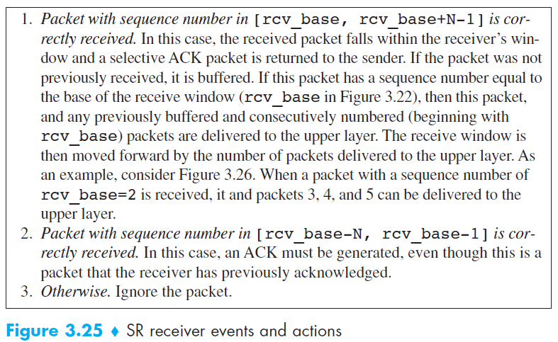
- Selective Repeat (SR):
- The receiver buffers out-of-order packets and sends an ACK for every correctly received packet.
- When a timeout occurs, the sender resends only the specific unacknowledged packet, not the entire window.
- The receiver requires a buffer to hold out-of-order packets until they can be delivered in order.
- Go-Back-N (GBN):
Drawback
The lack of synchronization between sender and receiver windows
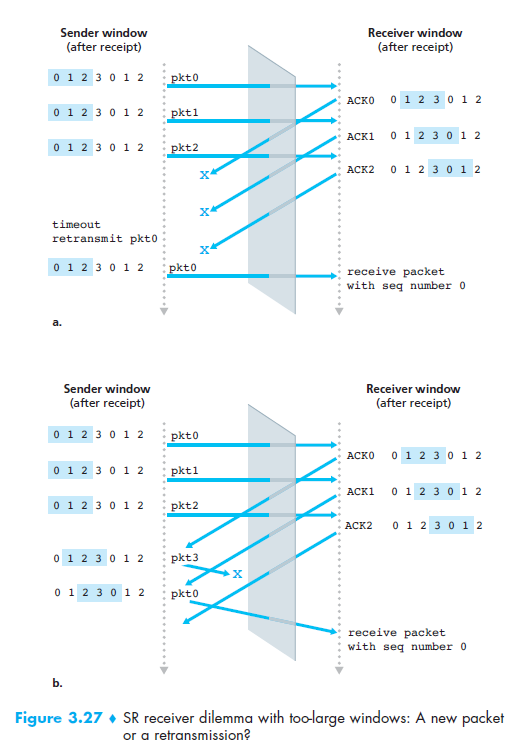
Solution, use window-size ≤ N/2
6. Connection-Oriented Transport: TCP
- Q1: Why is TCP considered connection-oriented?
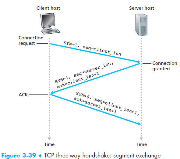
Two processes must first “handshake” with each other before one application process can begin to send data to another, “handshake” often referred to as a three-way handshake.
A TCP connection is also always point-to-point
- Q2: Which communication protocols does TCP provide?
- A TCP connection provides a full-duplex service
- Q3: What is buffer?
Created during the initial three-way handshake
Each TCP connection has its own send buffer and receive buffer
- Q4: What is Maximum Segment Size (MSS)?
It is the maximum size of application-layer data (payload) that TCP can place into a TCP segment.
Not including TCP header + IP header.
Q5: TCP Segment Structure
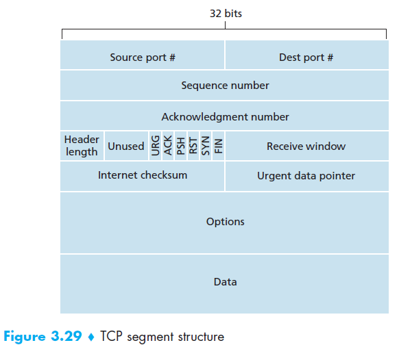
Q6: What are important fields in TCP Segment Structure?
- Two of the most important fields in the TCP segment header are the sequence number field and the acknowledgment number field
- Q7: What is TCP’s perspective about data?
- TCP views data as an unstructured but ordered stream of bytes
6.1 The sequence number field
- Sequence numbers in TCP are assigned over the byte stream, not over the segments themselves.
- The sequence number for a segment is therefore the byte-stream number of the first byte in the segment
- Example:
- Suppose there is a file of 500,000 bytes to send.
- MSS = 1,000 bytes (so each segment can carry up to 1,000 bytes of application data).
- TCP splits the file into 500 segments, each with 1,000 bytes.
- The sequence number of a segment is the byte-stream number of its first byte:
- Segment 1: starts at byte 0 → Sequence Number = 0
- Segment 2: starts at byte 1000 → Sequence Number = 1000
- Segment 3: starts at byte 2000 → Sequence Number = 2000
- … up to Segment 500: starts at byte 499,000 → Sequence Number = 499,000
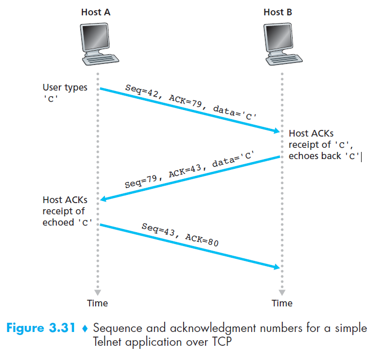
6.2 The acknowledgment field
Acknowledgment (ACK) number = the sequence number of the next byte expected.
Since TCP is full-duplex, each side (Host A and Host B) maintains its own sequence numbers and acknowledgment numbers independently.
When Host A sends a segment to Host B, it includes an ACK number telling B:
👉 “I have received everything up to byte X–1, and now I expect byte X.”
Example:
- Host A received a byte-stream from 0 to 535 by host B.
- Expected next byte A waiting for is 536.
- Then A send a segment to B, in header will have:
- ACK = 536
Q8: Three-way handshake?
Q9: Telnet example
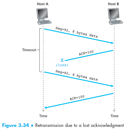
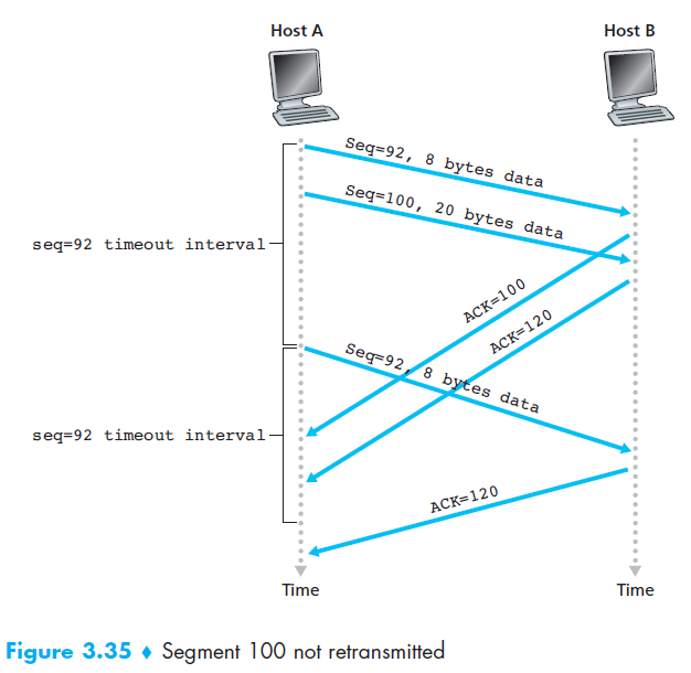
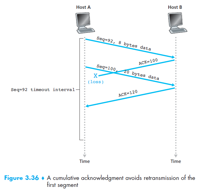
6.3 TCP RDT A Few Interesting Scenarios
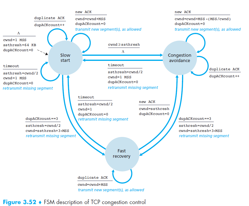
7. Congestion control algorithm
- TCP uses end-to-end congestion control because IP does not provide feedback about congestion.
- Idea: The sender adjusts its sending rate based on perceived congestion.
- If the network seems uncongested → increase send rate.
- If congestion is detected → decrease send rate.
- If the network seems uncongested → increase send rate.
- Congestion events:
- Timeout (loss detected)
- 3 duplicate ACKs
7.1 Slow start
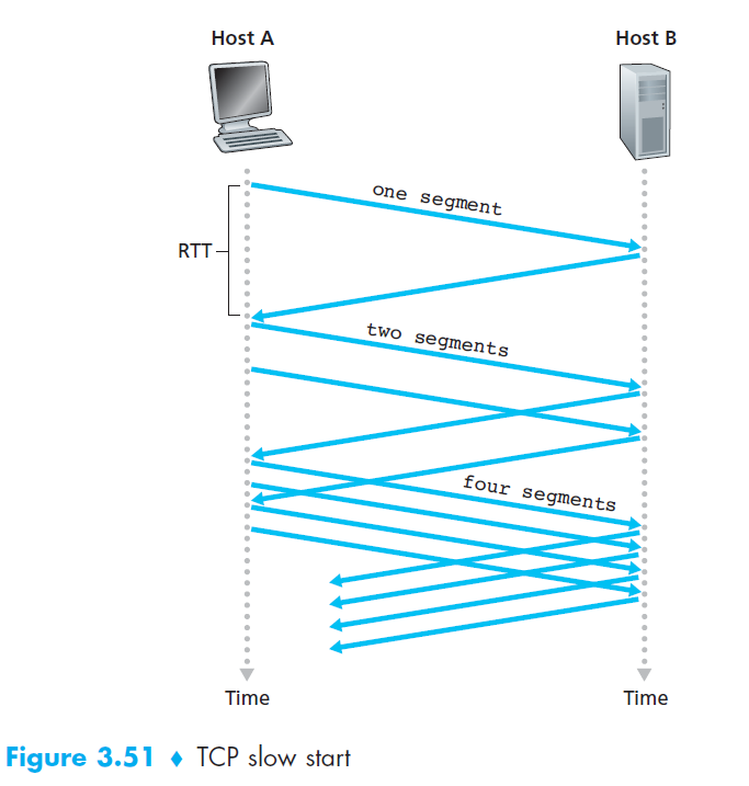
- Initialization
cwndstarts at 1 MSS (≈ MSS/RTT send rate).- Example: MSS = 500B, RTT = 200ms → initial rate ≈ 20 kbps.
- Growth Phase
- Each ACK →
cwnd += 1 MSS. - Sending rate doubles every RTT (exponential growth).
- Example: after 1 ACK →
cwnd=2, then 4, 8, 16…
- Each ACK →
- Ending Slow Start
- Timeout (loss detected):
- Set
cwnd = 1 MSS(restart slow start). - Set
ssthresh = cwnd/2(congestion threshold).
- Set
- cwnd ≥ ssthresh:
- Exit slow start.
- Enter Congestion Avoidance (linear growth).
- 3 duplicate ACKs:
- Perform Fast Retransmit.
- Enter Fast Recovery.
- Timeout (loss detected):
7.2 Congestion Avoidance
- Initialization
- Entered when
cwnd ≥ ssthreshafter Slow Start. cwndstarts at current value (≈ ssthresh).
- Entered when
- Growth Phase
- Each ACK →
cwnd += MSS * (MSS / cwnd)(≈ linear growth of 1 MSS per RTT). - Sending rate increases cautiously to avoid congestion.
- Each ACK →
- Ending Congestion Avoidance
- Timeout (loss detected):
- Set
cwnd = 1 MSS(restart Slow Start). - Set
ssthresh = cwnd / 2.
- Set
- 3 duplicate ACKs:
- Perform Fast Retransmit.
- Halve
cwnd(add 3 MSS for the triple-ACKs). - Enter Fast Recovery.
- Timeout (loss detected):
7.3 Fast Recovery (RENO)
- Initialization
- Entered after 3 duplicate ACKs during Congestion Avoidance.
cwnd= ssthresh + 3 MSS.
- Recovery Phase
- Retransmit lost segment immediately (Fast Retransmit).
- For each additional duplicate ACK →
cwnd += 1 MSS(keeps sending new segments).
- Ending Fast Recovery
- Upon receiving ACK for all outstanding segments:
cwnd = ssthresh(resume Congestion Avoidance).
- Upon receiving ACK for all outstanding segments: